| Home | Contents | Start | Prev | 1 | 2 | 3 | 4 | 5 | 6 | 7 | 8 | 9 | Next |
Construction
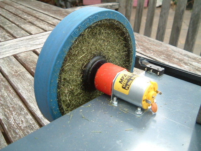
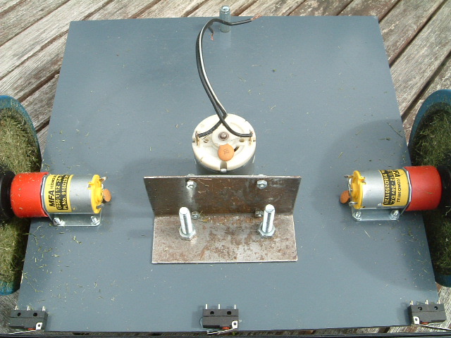
Driving Motors
The driver motors were mounted using small 3mm bolts through the PVC chassis. The motors were on top of the chassis to keep them out of all the grass debri that will be generated on the bottom of mower.
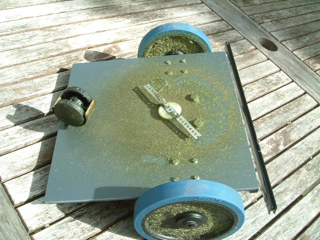
Castor
I had a castor from some old furniture. It is perhaps not as heavy duty as I'd have liked, and it may get stuck when reversing but it will do for now. One small mounting hole was drilled at the back of the chassis to accommodate it.
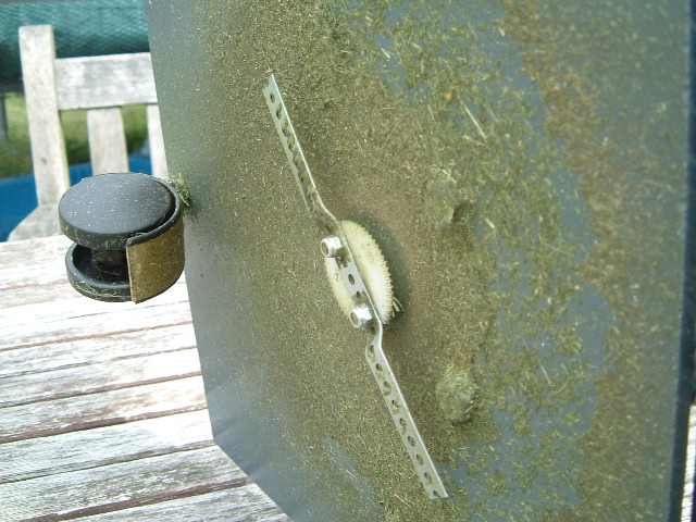
Cutting Motor
A fairly substantial steel bracket was made that allowed the cutting motor to mounted on top of the chassis with the shaft pushed down through a hole in the PVC to where the cutting blade would be. The cutting blade was mounted on a plastic gearwheel and gave a tight interference fit on the shaft.
Battery Mounting
I've never been a fan of glue, I find it does not lend itself to easy dismantling and maintenance and is likely to fail just when you dont want it to. However, in this case, I would like to minimize the number of bolts I put through the chassis as these just form potential collection points for cut grass and could clog the mower. In order to secure the battery from moving around I glued a retaining gutter made of lengths of wood onto the chassis just behind the cutting motor. This keeps most of the weight just behind the drive wheels in the centre of the platform.
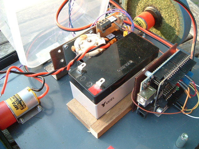
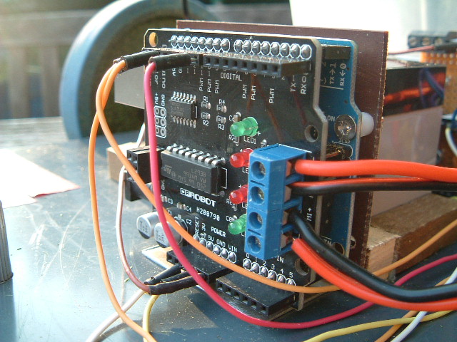
Microcontroller stack
The arduino and motor driver were secured using an aluminium backet mounted just behind the battery. It was mounted to one side to give room from power and USB cables to be attached.
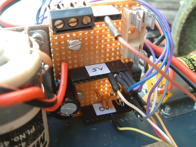
Relay and Distribution Boards
These were mounted on the same steel bracket that was used to hold the cutting motor, just in front of the battery. I may find that vibration from the motor may cause issues later but my goal was to mount al the electronics, the battery and the cutting motor in a central island so they can be covered with a plastic case (onto which a solar panel can be mounted). If vibration does cause a problem, I think I'll move all the electronics into a sealed box with rubberized mounts. However, that is Plan-B.

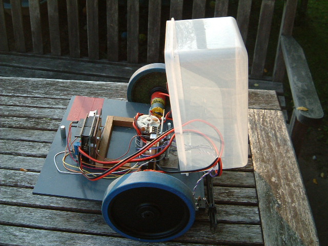
Weatherproofing
The mower is not really intended to stand outside in all weathers as trying to mow snow or wet grass is probably not a good idea. I do however, want some form of weather proofing so it can withstand cut grass flying around and the occasional shower. This is mainly so it can be left charging on the lawn while I am elsewhere and not have to worry about rescuing it if it starts raining. From the outset, I decided to try and give the battery, the circuit boards and the cutting motor some degree of weatherproofing. The drive motors being close to the wheels will have to look after themselves. The same goes for the microswitches. I have had a small geared motor open to the elements on top of the wendy house for about 5 years and it is still going strong so they should be fairly robust. Mounting a solar panel over the top of the mower should give an extra layer of protection that will also afford some shelter to the motors and switches.
The core components were mounted on an island in the centre of the mower. I used a large plastic box that covers them and hinged it to gain access to the components underneath, passing any wires through one opening near the front of the mower. I'm not going to go banzai over creating a watertight seal, a simple strip of rubber or braid of glue should be sufficient.
Software
The software to drive the mower is fairly straightforward. There are two distinct parts of the code, one that deals with monitoring sensors and taking evasive action if the bump sensors are activated, and one that monitors battery voltage. The main processing loop of the application is thus:
void loop() {
  monitorBattery();
  readBumpSensors();
  process();
}
Where process() will take action on the bump sensor readings if the battery is sufficiently charged. The state of the bump sensors determines the action taken by the mower. If one of the edge switches is activated, it will turn away from that switch (eg, if right switch activated, turn to the left). If either the centre or both edge switched are activated, reverse and turn around. Currently there is no randomness in the turns, a deterministic value is used.
No interrupts are used, just the polling interval of the main loop function which should be perfectly adequate in this application. I spent time making sure the switches were de-bounced in software. I don't really think this is necessary (and it does add a little latency) but it may help false triggering due to electrical noise as there will be three motors in close proximity to the electronics.
Arduino pins used:
const int LHF_SW = 12;               // Left Hand Front microswitch (IN)
const int RHF_SW = 13;               // Right hand front microswitch (IN)
const int CF_SW  = 8;                // Centre front microswitch (IN)
const int BATTERY_LEVEL = A0;        // Monitors battery voltage (IN)
const int BLADE_MOTOR = 10;          // cutting blade motor (OUT)
const int M1_DIR = 7;                // Motor1 direction control (OUT)
const int M1_PWM = 6;                // Motor1 speed control (OUT)
const int M2_DIR = 4;                // Motor2 direction control (OUT)
const int M2_PWM = 5;                // Motor2 speed control (OUT)
Battery Monitoring
A potential divider will be used to bring the battery volt battery voltage down to the 5V range for monitoring. An analogue input to the arduino will monitor this voltage and shutdown if it falls below a minimum threshold.
Having 12 NiMH batteries in series and assuming the max charge per battery = 1.45v and the minimum allowed is 1.0v, we just need to shutdown the motors when battery voltage becomes too low and stay in this state. The mower will then be turned off to allow charging whereupon it will reset.
    /* Assume max charge = 1.45 * 12 = 17.4 volts.
    ** Potential divider = 22k + 82k gives
    ** 33(33+82) = 0.287.
    ** 17.4 * 0.287 = 4.99 volts.
    ** need to shutdown when cell voltage drops to 1v
    ** 1 * 12 = 12 volts.
    ** so 12 * 0.287 = 3.45 volts.
    ** 5v  is represented by 255 in digital.
    ** 3.45/5 * 255 = 176. Therefore this is the digital threshold.
    */
July 2012
| Home | Contents | Start | Prev | 1 | 2 | 3 | 4 | 5 | 6 | 7 | 8 | 9 | Next |