| Home | Contents | Start | Prev | 1 | 2 | 3 | 4 | 5 | 6 | 7 | 8 | 9 | 10 | 11 | 12 | 13 | 14 | 15 | 16 | 17 | 18 | 19 | 20 | 21 | 22 | 23 | 24 | 25 | 26 | Next |
Determining Orientation
My current thoughts are that the robot will try and mow on a fixed compass bearing. This will hopefully achieve mowing in straight lines. A digital compass is all I really need for this but at some stage, it may be useful to measure tilt to determine if the slope is too steep to safely mow. An accelerometer can be used to measure tilt, or I could just use a basic tilt switch.
Since I wanted a digital compass and may later need an accelerometer, I started searching for modules that combined this functionality and came across this sparkfun IMU 9 DOF board based on the LSM9DS1. This device contains an integrated 3 DOF magnetometer (compass), a 3 DOF accelerometer and a 3 DOF gyroscope. The sensitivity of each device can be adjusted. That is an impressive amount of technology on one board! As the devices are integrated, it should mean a lot of the mathematics to combine their outputs will be taken care of either in software or hardware so I may get a digital compass which has accelerometer/gyro corrections built in.
Interfacing to the IMU
The LSM9DS1 is full blown Inertial Measurement Unit (IMU) but (for now), I am only interested in getting a compass bearing out of it. If behind the scenes, the gyro and accelerometer correct for tilt, all the better, but I am focused solely on the compass. The board generates interrupts as each device makes measurements available so is very versatile. I will initially just poll the compass reading as that may be more than enough for my needs and can always dive deeper if necessary.
The LSM9DS1 supports both SPI and I^2C interfaces. I will use the I^2C interface as that requires the minimum of wiring. Sparkfun also provide a library to interface to the board. Part of me wants to dive deeper into the guts of this device, but I am trying to achieve a higher level goal (namely mowing on a compass bearing), so I will swallow my curiosity for now and use the library.
Testing the Compass
Well, sparkfun have provided a library that has enough goodies in that using the compass is trivial, they really have made it very simple to use. I soldered some header pins to the board, connected via the I^2C bus, loaded the example code and it worked out of the box on a Uno.
Some simple cutting and pasting into the Moana project and I soon had a getHeading() function that would return the heading as a value between 0 and 359 degrees. New Zealand has quite a large magnetic declination (nearly 20 degrees east) which I can add to the program, but as everything is relative for steering, it is really not that important.
Compass Mounting - Thoughts
Although I have not used a digital compass before, I'm aware of many of pitfalls that come with using a normal compass and think I will save a lot of headaches if the compass is mounted away from the main body of the mower. Magnetic materials like screws and bolts should be avoided and the electromagnetic fields generated by the mower's motors may also cause interference. In addition to this, it is necessary to ensure the compass is mounted aligned correctly with the mower, and as horizontal as possible. Sloped ground may cause problems but I will tackle that when it arises. I suspect the GPS unit may benefit from being away from the electromagnetic swamp that forms the heart of the mower so the two could be mounted together.
The compass will be mounted on a non-ferrous pole that will sit above the main carcass of the mower. I feel I may have lots of teething problems here so my plan it to mount it on a wooden dowel that can be twisted to align the compass with the mower and later fixed in place. It may be necessary to make something more robust afterwards bit this seems a good place to start.
Compass Mounting - Implementation
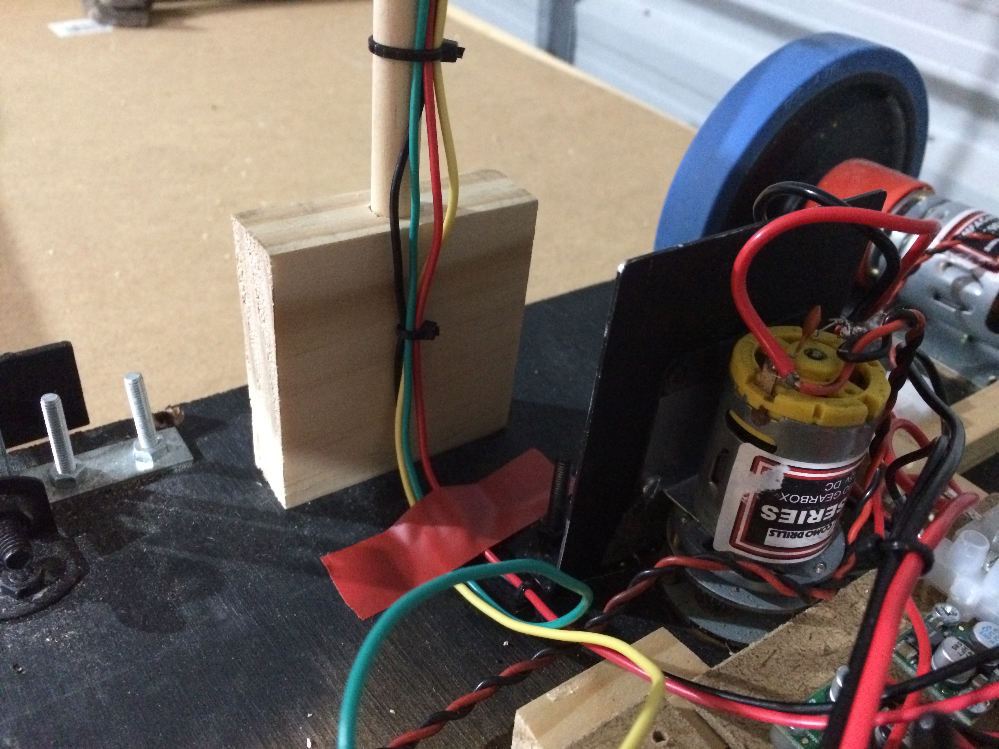
Time has been a premium so I have had to approach this in a pragmatic manner. I used a 10mm dowel as the tower and mounted this in a block of wood which was screwed to the chassis. The dowel has an interference fit into the wooden block, the idea being that it can be twisted to align the compass with the mower. At the other end, the compass was mounted on wooden block with plastic bolts. I intended to mount this directly onto the dowel with a brass screw but didn't have any so changed to use an interference-fit wooden block. See diagrams below.
This is the base of the compass tower
This is the top of the compass tower
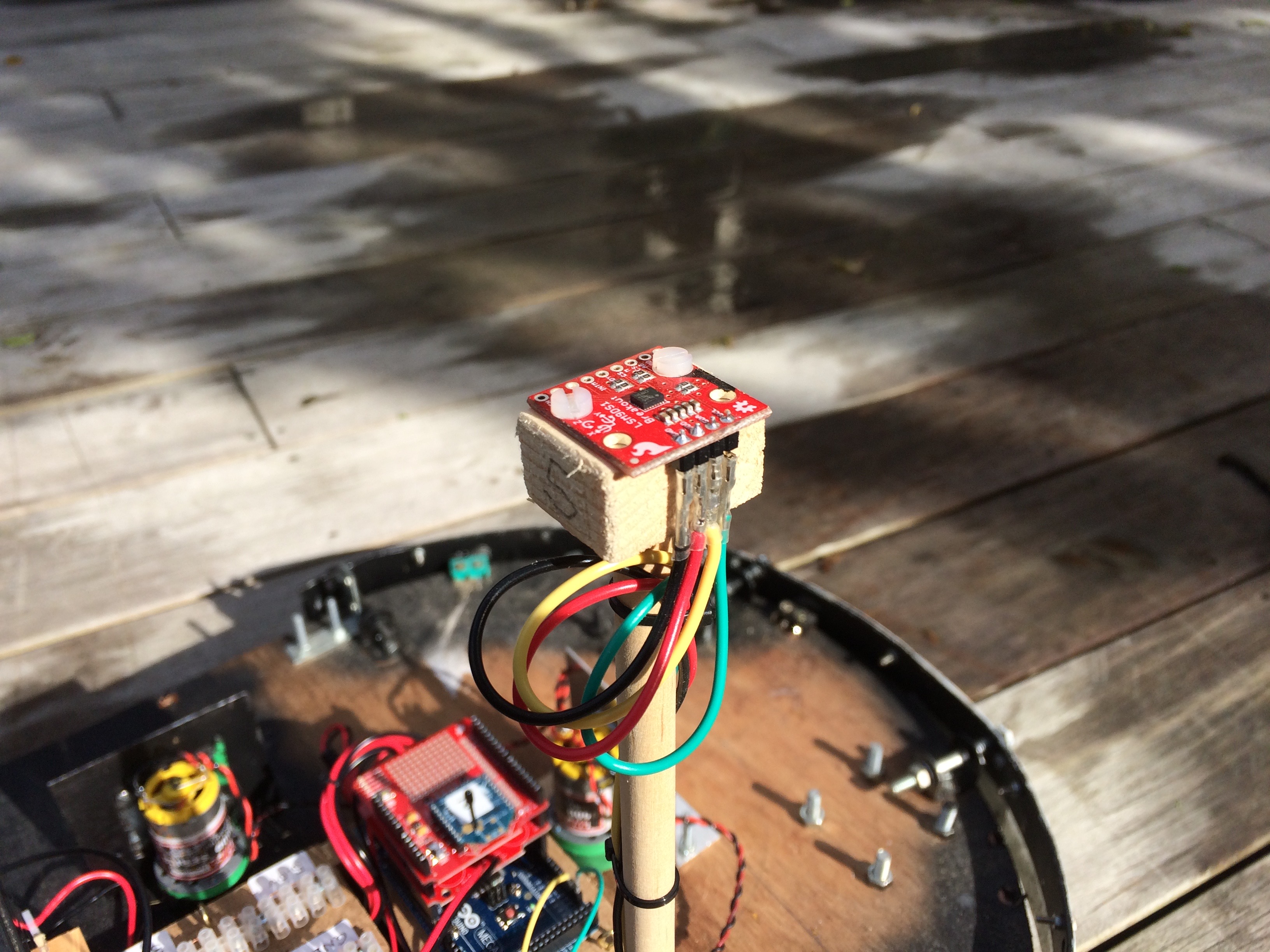
The tower should not hinder taking the cover off the mower so wires are brought down the tower and come under the cover. Note that the compass is a 3.3v device so it is powered from that block on the power distribution board. After connecting up to the SCL and SDA tins on the Mega (these are different pin locations to the Uno), we are ready to run some tests.
April 2018
| Home | Contents | Start | Prev | 1 | 2 | 3 | 4 | 5 | 6 | 7 | 8 | 9 | 10 | 11 | 12 | 13 | 14 | 15 | 16 | 17 | 18 | 19 | 20 | 21 | 22 | 23 | 24 | 25 | 26 | Next |